
A pneumatic diaphragm three-way control valve can be designed for mixing two streams or diverting one stream between branches. The common port, permitted flow directions and trim arrangement must match that task. A windowed plug or a particular seat layout is one design option, not the construction of every three-way valve. Heat-exchanger bypass control is a common application, but it is not automatically two-phase flow control.
Working principle of pneumatic diaphragm three-way regulating valve
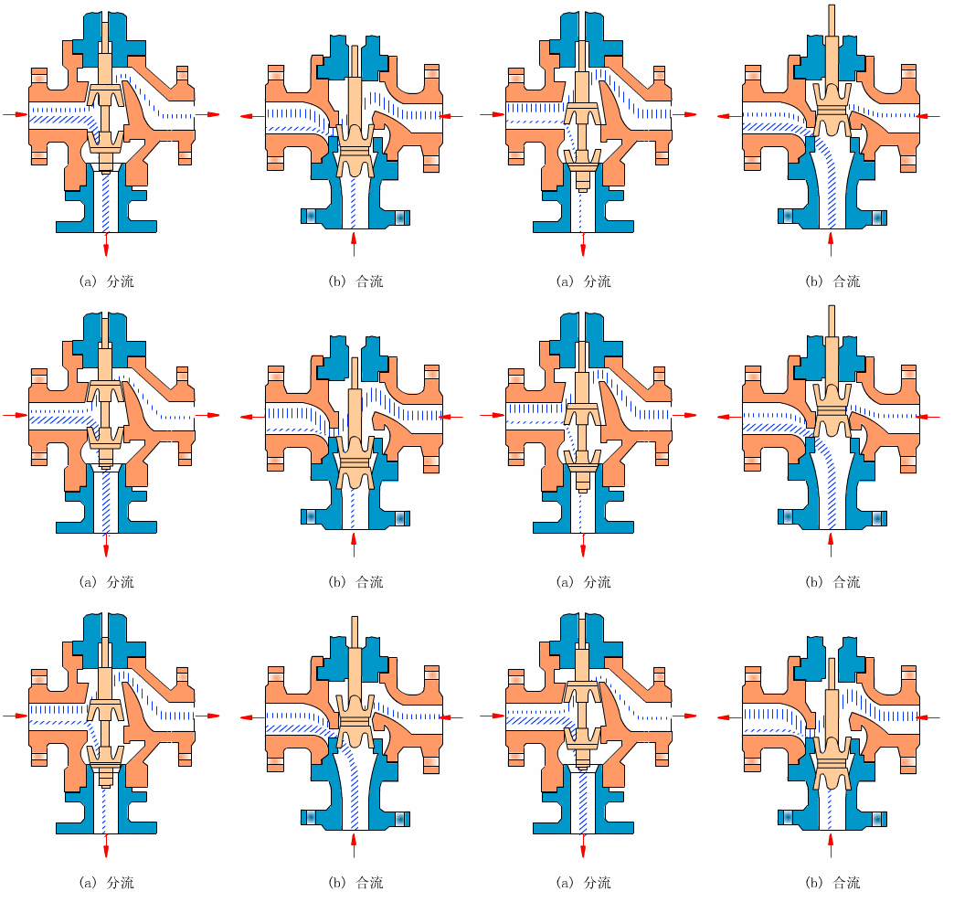
The diaphragm actuator converts pneumatic pressure into stem force. An electro-pneumatic positioner uses the control demand and travel feedback to regulate the actuator air. A common input is 4–20 mA; other inputs depend on the selected device. The electric signal does not supply the pneumatic force, and 0–10 mA is not a universal requirement. Match minimum available air, spring action and output force to the valve load and required failure state.
Mixing and diverting designs can differ in plug, seat, guidance and hydraulic forces. Do not reverse connections based only on a generic sketch. Confirm the actual port drawing and evaluate minimum, normal and maximum flow with each branch pressure. The required flow coefficient and installed response depend on both branches, not only the main pipe size. Before replacing a two-valve arrangement, also assess bypass duty, isolation, maintenance access and the behavior after loss of air or control.
Frequently asked questions
Can a mixing valve be used for diverting by reversing the pipes?
Not without confirmation of the actual trim and permitted flow directions. Reversing the pressure forces can change stability, shutoff load and capacity. Use the supplier drawing for that configuration, not the port names from a generic diagram.
Does a 4–20 mA command mean the valve can move without instrument air?
No. The current communicates demand; the positioner and diaphragm actuator still need the specified pneumatic supply. Verify available pressure during movement and the complete air circuit, not only the control signal.
Which branch opens if instrument air is lost?
The result depends on the trim, actuator action, spring arrangement and control accessories. Define the required flow path for the process and obtain a configuration-specific failure-state diagram. A simple air-to-open label does not describe every port.