Construction and motion
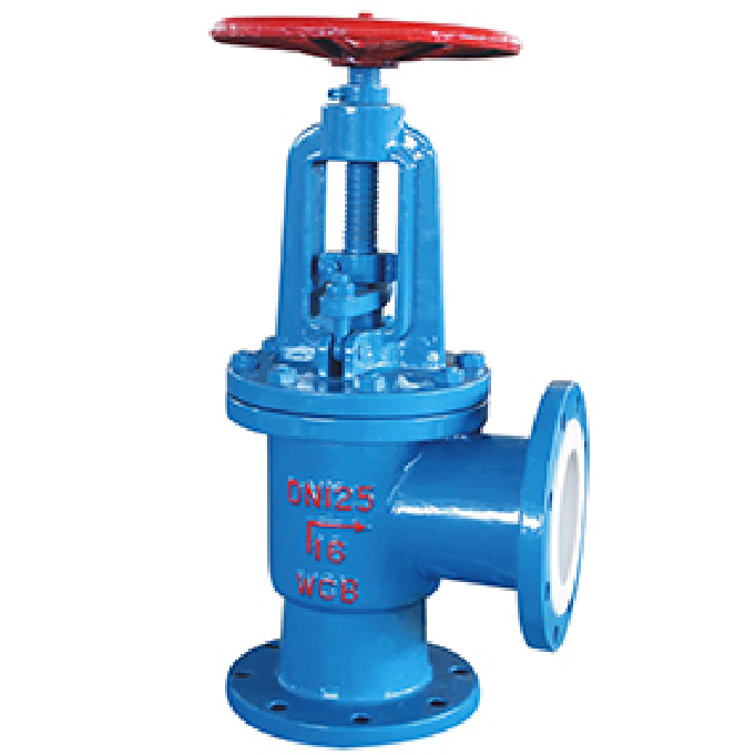
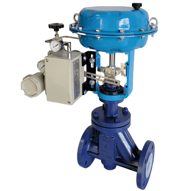
The lined flanged control valve uses a pneumatic diaphragm actuator and linear stem movement. Air pressure produces axial thrust to position the plug relative to its seat. Select by required thrust, travel, available air supply and loads from differential pressure, seating and packing friction, not rotary torque alone.
Body and lining are separate
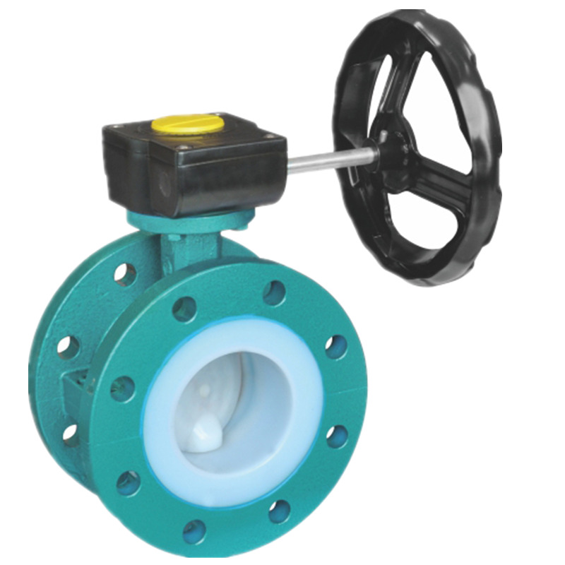
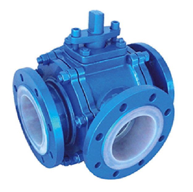
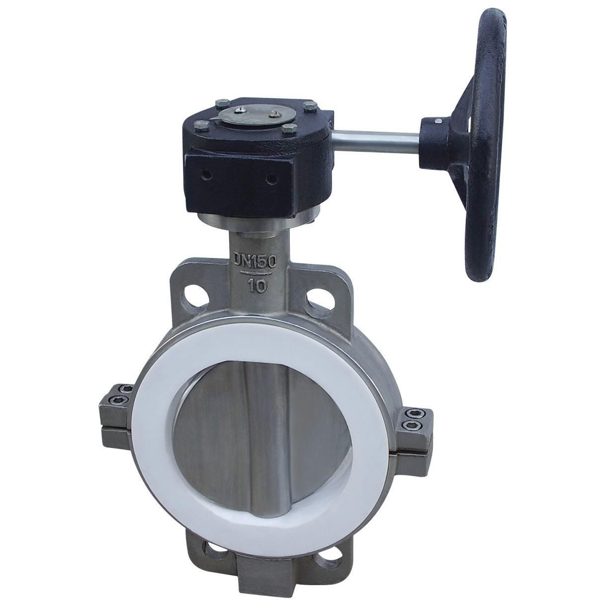
The metal body carries structural and pressure loads; the process-side lining is specified as PFA, FEP or PTFE. These are different fluoropolymers. The presence of a lined body does not mean that the positioner is itself lined with PTFE.
Class 150 and limits
Class 150 is not a fixed PN16–PN20 equivalent or a constant operating pressure. Check material, temperature, applicable standards and limitations of the lining, seals and complete valve.
Positioner and flow control
The positioner compares a command with stem position and controls actuator air. A 4–20 mA input is an option for a suitable electropneumatic positioner, not a universal signal requirement or a guarantee of exact flow. Confirm inputs, feedback and failure position for the chosen equipment.
Sizing information
Provide fluid composition, temperature, minimum/normal/maximum flow, upstream and downstream pressures and required shutoff conditions. Confirm Cv/Kv, trim characteristic, stroke, thrust, lining and test requirements from the actual calculation and supply documents.
Enquiry and technical documents
Provide fluid composition, normal and maximum pressure and temperature, flow, size, connections and operating requirements. Verify the selected data sheet, assembly drawing, material documents and agreed tests; do not transfer ratings from a different product.