

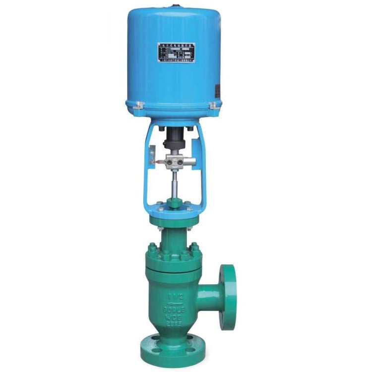
Angle body and linear control motion
This catalogue item combines an angle-pattern flanged valve body with an electric linear actuator. The actuator moves the stem and trim axially to vary the flow opening. The turn in the body flow path is not a quarter-turn actuator motion. Confirm the offered trim, required thrust, travel and permitted flow direction against the actual assembly drawing.
Electrical options must match the ordered actuator
The existing catalogue lists a single-phase AC 220 V supply and a 0-10 mA input option. These are configuration references, not a universal wiring specification. Confirm supply voltage and frequency, input and feedback signals, controller compatibility, enclosure and site requirements on the selected actuator data and wiring diagram. A current input must not be relabelled as a voltage input; a 4-20 mA option requires a suitable confirmed module.
Size the control duty and verify the interface
Supply minimum, normal and maximum flow cases with inlet and outlet pressures, temperature, fluid phase and relevant properties. Ask for the selected flow-capacity and trim data and a review of cavitation, flashing, choking or noise where relevant. Confirm flange standard, facing and centre-to-face dimensions from the ordered drawing. Do not mix flange and welding-end options or apply one generic size, PN/Class or temperature envelope to all assemblies.
Define loss-of-power behaviour
State the process-required position on loss of power or control signal, manual-override needs and operating frequency. The words electric actuator do not establish a fail-open or fail-closed function. Agree the actual control arrangement and commissioning checks before supply.
Frequently asked questions
Can I connect a 4-20 mA controller directly?
Only after the offered actuator or control module is confirmed to accept that signal. Check the input range, wiring and feedback separately; the published 0-10 mA option is not the same as 0-10 V or 4-20 mA.
Will the valve automatically close if power is lost?
Not necessarily. Specify the required safe position and have the supplier confirm the mechanism, power arrangement and loss-of-signal behaviour of the ordered assembly.
Is choosing the same nominal size enough for a control-valve replacement?
No. Provide the operating flow cases, differential pressures, fluid conditions, trim requirements and electrical interface, as well as the piping dimensions, so the offered assembly can be checked.
General technical references—not product certificates: Control-valve standards and dimensional scope
Prepare a quotation for this valve
Separate process sizing, piping geometry and the electrical interface when requesting an electric angle control valve.
- Process cases
For minimum, normal and maximum duty, supply flow, inlet/outlet pressures, temperature, fluid phase and relevant fluid properties with units. Identify startup and upset cases separately.
- Piping and trim
Send size, flange standard/facing, angle layout and available centre-to-face space. State desired shut-off duty and any erosion, cavitation, flashing or noise concern.
- Electrical and control
State available voltage/frequency, command signal, feedback, local/remote control, operating frequency, enclosure and hazardous-area requirements if applicable. Agree the actual actuator/module configuration.
- Loss-of-energy requirement
Specify the valve response required on loss of power or signal, together with manual override and commissioning requirements. Select the actuator and control arrangement for that response.
Documents to agree before supply
- Selection calculation and offered trim/flow-capacity data with the specified operating cases
- Assembly outline, stem travel and actuator thrust/mounting details
- Order-specific electrical data, terminal/wiring diagram and agreed power/signal-loss response
Ask which documents are available for the offered configuration and agree their scope before supply. A catalogue picture is not a certified drawing or test report.
Download a buyer enquiry checklist
Download this valve enquiry checklist (TXT). This is a fill-in purchasing worksheet, not a technical datasheet. Unknown values can be left blank.
Send an enquiry for this valve · cross-standard valve replacement checklist · Engineering selection and technical Q&A


