中外合资阀门品牌-致力于各类阀门的生产及研发。
[email protected] 0510-83129123
江苏泰科流体控制阀门有限公司

专业阀门制造商

询价

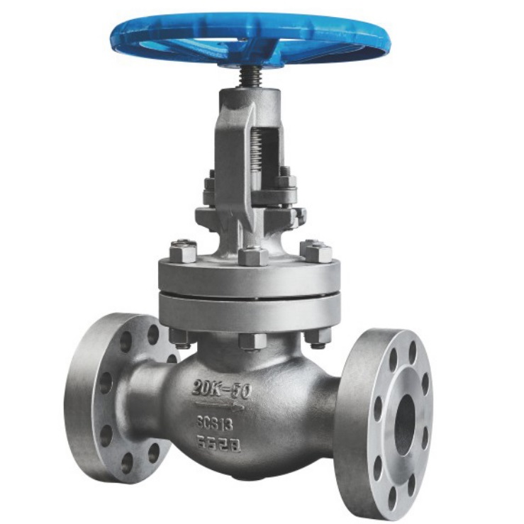
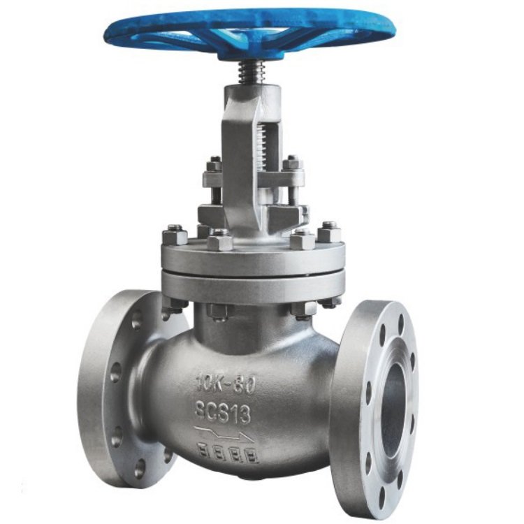
JIS 10K Japanese standard flange globe valve SCS13/SCS14/SCPH2

JIS 10K Japanese standard flange globe valve SCS13/SCS14/SCPH2

Product parameters

JIS 10K globe valve SCS13/CS14/SCPH2 flange globe valve specifications. The main material of JIS 10K globe valve is SCS13/CS14/CHPH2, which belongs to the flange globe valve. The pressure rating is 10K, the working pressure is 16 bar, and the valve body material is stainless steel or carbon steel. Before leaving the factory, we will conduct a water pressure test of no less than 18 bar for the sealed valve.

JIS 10K日标法兰截止阀SCS13/SCS14/SCPH2(图1)

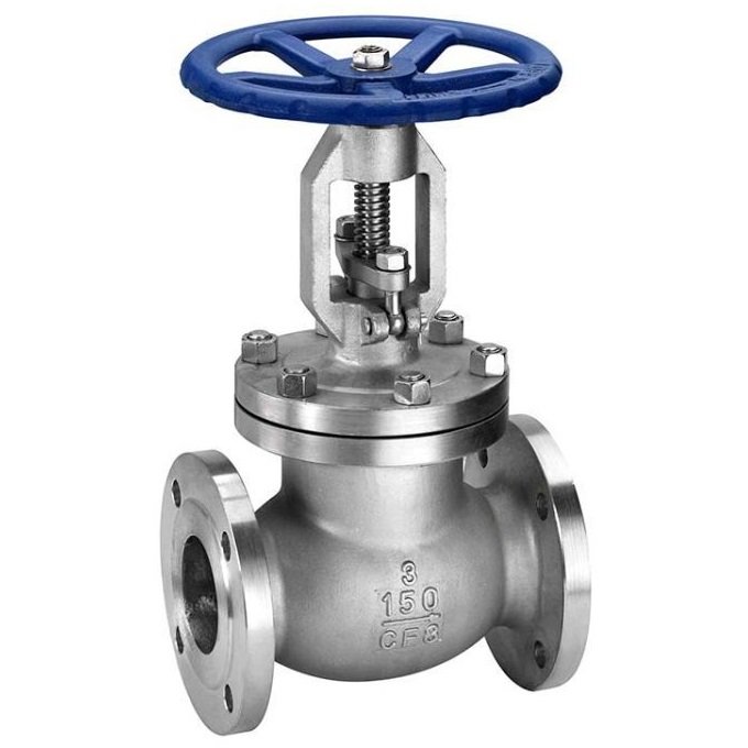
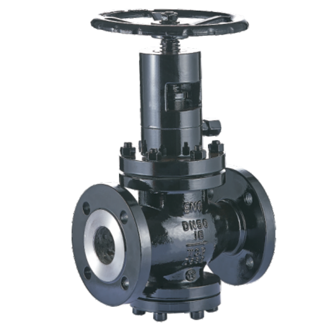
Chinese JIS 10K globe valve manufacturer JIS 10K日标法兰截止阀SCS13/SCS14/SCPH2(图2)NRS JIS 10K flange globe valve structure diagram. We are a valve manufacturer based in China, specializing in Japanese standard globe instruments. We offer a variety of pressure rating valves for customers to choose from. If you cannot find what you need on our website, you can contact us by email

The valve stem of the NRS JIS 10K flange globe valve/OS&Y JIS 10K flange globe valve is generally rotated up and down, and the handwheel is fixed at the top of the valve stem. When turning the handwheel clockwise, unscrew the valve stem thread, and the sealing surface of the valve disc is in close contact with the sealing surface of the valve seat. The globe valve is in the closed state; When turning the handwheel counterclockwise, the valve stem thread tightens and the valve plate closes. The sealing surface separates from the valve seat sealing surface, and the shut-off valve opens.

Turning the handwheel of the shut-off valve causes the valve stem to rise and fall, driving the valve disc to make a linear displacement parallel to the direction of medium flow, achieving the purpose of opening and closing

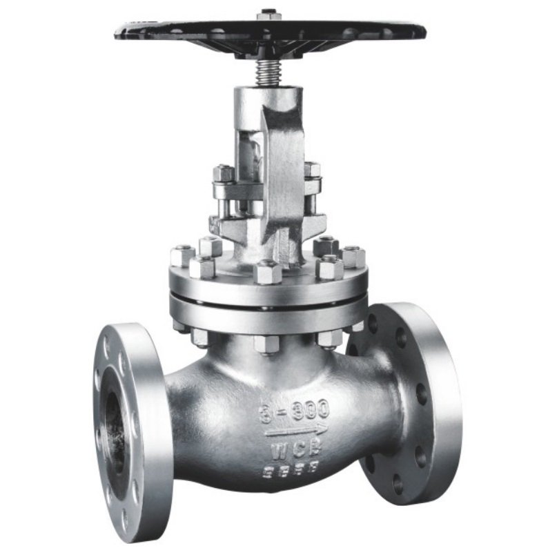
JIS 10K日标法兰截止阀SCS13/SCS14/SCPH2(图3)

NRS 15A-100A concealed stem daily standard globe valve NRS stem daily standard globe valve, with main sizes 15A-100A optional

JIS 10K日标暗杆截止阀SCS13

OS&Y 50A-500A rising stem daily standard globe valve OS&Y stem daily standard globe valve, main sizes 50A-500A optional

Body material: CHPH2, SCS13, SCS14NPS: NRS: 15A-100A OS&Y: 50A-500A Design standard: JIS B2071 Face to face: JIS B2002 Flange standard: JIS B2220 Inspection and testing: JIS B2003

JIS 10K flange globe valve, also known as JIS 10K flange globe valve, can prevent the flow of pipeline media.

JIS 10K Golbe valves usually have metal seats, or we can make the seat into an elastic seat and PTFE gasket according to customer needs

The working characteristics of the globe valve are that the sealing form of the 10k globe valve is forced sealing. When the valve is closed, sufficient force must be applied to the valve disc, and the seal must be above a specific pressure to achieve sealing. Due to the fact that the sealing force and medium pressure are on the same axis, when the medium enters from the lower part of the valve disc (low in and high out), the torque required to close the valve is much greater than the opening torque, and the valve stem bears greater pressure. The stress is compressive stress, so it must have sufficient strength and stiffness, otherwise the valve stem will undergo flexible deformation. Because of this, when the size of the globe valve is greater than DN150 (NPS16), in order to reduce the valve operating torque and thus reduce the valve stem diameter, the flow direction of the medium is usually changed from the upper part of the valve. The valve disc enters (high inlet and low outlet), and at this time, the medium pressure. In the same direction as the sealing force, under the action of medium pressure, the valve is more likely to achieve sealing, with a decrease in closing torque and an increase in opening torque. The larger stress on the valve stem is tensile stress, and the length of the diameter valve stem can be correspondingly reduced.

JIS 10K日标法兰截止阀SCS1
Tekron & Trekre

Stop valve

01 Why are stop valves suitable for throttling, while gate valves are not?
The core concept can be summed up in one sentence: The stop valve is like a faucet, allowing you to control the flow of water precisely by adjusting the opening degree; the gate valve is like a door, either fully open or fully closed; when it is partially open or closed, the water flow will "scrape" and damage the sealing surface of the gate plate.
The figure above has already shown the structural comparison between the two. The flow channel of the stop valve on the left is S-shaped (the fluid changes direction, which is itself a throttling principle), while the flow channel of the gate valve on the right is straight-through (the fluid does not turn, and the gate plate is suspended in the middle and is subject to erosion and vibration).
Selection rule: Use a stop valve for throttling and regulating; use a gate valve for full opening and full closure.
02 How to evaluate valve manufacturers?
The product's execution standards, pressure ratings and material ranges, valve body and internal component traceability, pressure and sealing test documents, flow direction and installation requirements, similar medium experience, and after-sales responsibilities should all be verified. The supplier should also provide a written confirmation of the selection based on the medium, temperature, pressure difference, diameter and regulation requirements.
03 What are the characteristics of stop valves and in which situations are they applicable?
The stop valve achieves cutting or regulation by the movement of the valve disc along the axis of the valve seat. It usually has good throttling characteristics, but the flow channel turns will result in higher pressure loss compared to the straight-through type valve. It is commonly used in steam, process media and pipelines requiring certain flow regulation; the specific structure, materials and flow direction should be determined according to the working conditions.